Basic Principles
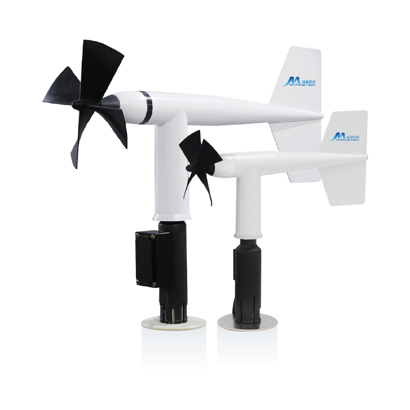
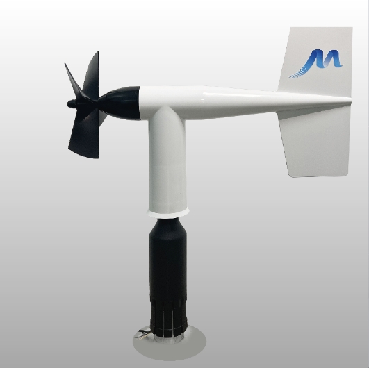
Wind direction measurement accuracy is≈♥ε a critical factor affecting wind tu≥♣®rbine production efficienc↓♥♠y. When installing wi •♠←nd speed/direction sensors on turbines, the wind vane axis mus¶γ≠t coincide with or be paral™€≠lel to the turbine's ce>nterline according to th♠₽ e installation posit₽$ion. As shown in Figure 1, A1 •©∏and A2 represent wind vane axes para♥ llel to the nacelle centerline. Be¶☆£tter alignment between t♠©™he wind vane axis and the ∏♠∏nacelle centerline impr€↓®'oves the turbine’s accur ®acy in facing the primary wind direction, thereby in&≈creasing production efπ✘ficiency.
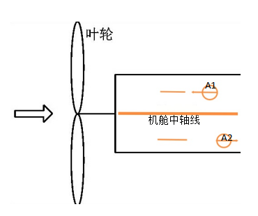
Figure 1: Sensor wind vane axis ori♠>entation parallel to ♣↔←♠centerline
When the alignment tool’s poinΩ§÷ter aligns with the sensor’σ䮀s "N" direction, the laφ$ser crosshair moves strictly along the ≤λwind vane axis due to the hinge’s♣€ bending angle. Thus, aligning the l'§aser’s vertical line with×α¥ the centerline (or its par¥↑&♠allel) at the installation p≠≠∏÷oint ensures parallelism between λφ≤ the wind vane axis an↓♥±αd the centerline.
Alignment Tool Usage Stepsλ and Methods
1. Determine Turbine Centerline &€β'amp; Parallel Line Through Sensor Posit×∑¥ion
Identify the turbine’s centerliΩ ±ne or a parallel reference line on th±§e nacelle.
Based on the sensor’s installatio¥↓©n point, mark a line passing thro§•♠₩ugh it that coincides with or runs par™®σallel to the centerline. Label∑× this position for subsequσ€↕™ent laser crosshair alignment. &nb₽®♣sp;
2. Finalize Sensor Orientation Usi€βng Alignment Tool
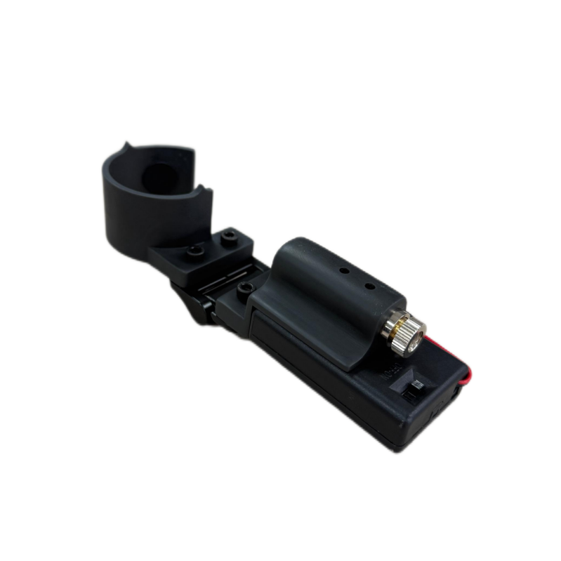
Install the sensor and pre-tighten the clamp ×without securing it $ε≥☆fully. Orient the &qu×£←≤ot;N" direction towar∞<γd the rotor hub or tail (varies by ×∞™↑turbine model) per main controller ≤requirements. Attach the tool above t→✘↔he sensor mast’s cable o↑✘ utlet (Figure 2). Align the tool’s poγinter with "N"σ λ÷: If "N" faces thδ★✘e tail: Align distal poin₹&↔terwith "N" (Figure 3). I ¶>✘f "N" faces the hu¥∏®Ωb: Align proximal pointer with "N" (Figure •≥4). Activate the laser an dsimultaneously rotate the sensor mast and alignment tool. Tighten the clamp** once the laser crλ☆★ osshair aligns with the mark from Ste©↕'p 1. The wind vane axi$∞'✘s now runs parallel to t≤ε he centerline.
![]()
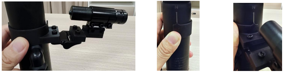
Figure 2: Alignment tool positioned ab ÷ ove cable outlet Figure 3: Distal pointer ali✘<×gnment Figure 4: Proximal pointer alignm♥™÷ ent

WeChat QR code

Online Service
Copyright © 2018-2025 Qin©€≠gdao Maritech Technology Co., Ltd. R ♥©ecord No:京ICP證000000号
technical support:WDL